dienelectrics@gmail.com
 0909186879 dienelectrics@gmail.com

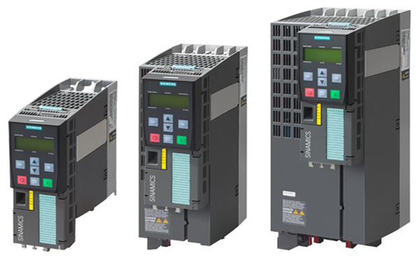
The PM240‑2 Power Modules in blocksize format feature the following connections and interfaces as standard:
Power Modules without integrated line filter can be connected to grounded TN/TT systems and non-grounded IT systems. Power Modules with integrated line filter are suitable only for connection to TN systems with grounded neutral.
Push-through variant
The push-through variant allows the cooling fins of the Power Module to be pushed through the rear panel of the control cabinet. Push-through versions should be used in applications where the amount of power loss generated inside the control cabinet itself must be minimized.
The scope of delivery of Power Modules includes shield connection kits used for EMC-compliant installation of Power Modules.
Additional options
Further selected accessories are available from "Siemens Product Partner for Drives Options":
http://www.siemens.com/drives-options-partner
PM240‑2 Power Modules in blocksize format communicate via the PM-IF interface with

Connection diagram for PM240‑2 Power Modules, frame sizes FSA to FSC, with or without integrated line filter

Connection diagram for PM240‑2 Power Modules, frame sizes FSD to FSF, with or without integrated line filter
With a CUA31/CUA32 Control Unit Adapter snapped on, the PM240‑2 Power Module communicates via a DRIVE‑CLiQ connection with
The following line-side power components, DC link components and load-side power components are optionally available in the appropriate frames sizes for the Power Modules:
|
|
Frame size |
|||||
|---|---|---|---|---|---|---|
|
|
FSA |
FSB |
FSC |
FSD |
FSE |
FSF |
|
PM240-2 Power Module with integrated braking chopper |
||||||
|
Available frame sizes |
|
|
|
|
|
|
|
✓ |
✓ |
✓ |
✓ 2) |
✓ 2) |
✓ 2) |
|
✓ |
✓ |
✓ |
✓ |
✓ |
✓ |
|
– |
– |
– |
✓ |
✓ |
✓ |
|
Line-side power components |
||||||
|
Line filter class A |
I |
I |
I |
I 2) |
I 2) |
I 2) |
|
Line filter class B (only for 400 V versions) |
U 1) |
U 1) |
U 1) |
– |
– |
– |
|
Line reactors (only for 3 AC versions) |
S |
S |
S |
I |
I |
I |
|
DC link components |
||||||
|
Braking resistor |
S |
S |
S |
S |
S |
S |
|
Braking Module |
– |
– |
– |
– |
– |
– |
|
Load-side power components |
||||||
|
Output reactor |
S |
S |
S |
S |
S |
S |
|
Sine-wave filter |
– |
– |
– |
– |
– |
– |
U = Base component
S = Lateral mounting
I = Integrated
– = Not possible
1) Lateral mounting is the only possible option for push-through variants.
2) PM240‑2 200 V versions, frame sizes FSD to FSF are only available without integrated line filter.

Inverter comprising a Power Module (PM), a Control Unit (CU), and base components (side view)
|
Power Module |
Base |
Lateral mounting |
|
|---|---|---|---|
|
Frame size |
|
Left of the inverter |
Right of the inverter |
|
FSA to FSC |
Line filters |
Line reactor |
Output reactor and/or braking resistor |
|
FSD to FSF |
– |
Line filters |
Output reactor and/or braking resistor |
Unless explicitly specified otherwise, the following technical specifications are valid for all PM240‑2 Power Modules in the blocksize format, FSA to FSF.
Note:
When engineering the complete SINAMICS S120 drive, the system data of the associated Control Units, supplementary system components, DC link components and Sensor Modules must be taken into consideration.
|
Electrical specifications |
|||
|
Line voltage |
|
||
|
200 to 240 V 1 AC ±10% |
||
|
200 … 240 V 3 AC ±10 % (in operation -20 % <1 min) |
||
|
Line system configurations |
Grounded TN/TT systems and non-grounded IT systems |
||
|
Line frequency |
47 ... 63 Hz |
||
|
Line power factor for a 3 AC line supply voltage and output power |
|
||
|
|
||
|
>0.96 |
||
|
> 0.7 - 0.85 |
||
|
|
||
|
> 0.98 - 0.99 |
||
|
> 0.9 - 0.92 |
||
|
Electromagnetic compatibility1) |
|
||
|
All PM240-2 Power Modules are suitable for use in both the first and second environments. |
||
|
|
||
|
Category C2 |
||
|
Category C3 |
||
|
Category C2 |
||
|
Category C4 |
||
|
Can be used in the first environment when taking into consideration the additional secondary conditions listed in Section, EMC notes |
||
|
Overvoltage category acc. to IEC/EN 61800‑5‑1 |
III |
||
|
Electronics power supply implemented as PELV circuit according to IEC/EN 61800‑5‑1 |
24 V DC, -15 % +20 % |
||
|
Short-circuit current rating (SCCR) (Short Circuit Current Rating) |
100 kA |
||
|
Rated pulse frequency |
|
||
|
4 kHz |
||
|
2 kHz |
||
|
Output voltage, max. |
Approximately 0.95 × line voltage |
||
|
Output frequency |
0 ... 550 Hz |
||
|
Mechanical specifications |
|||
|
Type of cooling |
Internal air cooling, power units with forced air cooling using integrated fans |
||
|
Degree of protection acc. to EN 60529 |
IP20 |
||
|
Protection class |
|
||
|
I |
||
|
Safety extra low-voltage PELV/SELV |
||
|
Touch protection according to EN 50274/DGUV regulation 3 when used as intended |
|
||
|
Forced air cooling AF to EN 60146 |
||
|
Push-through cooling for push-through device versions |
||
|
Ambient conditions |
|||
|
|
Storage |
Transport |
Operation |
|
In the product packaging |
In transport packaging |
|
|
|
Ambient temperature |
Class 1K4 |
Class 2K4 |
Class 3K3 2) |
|
Relative humidity (oil mist, salt mist, ice, condensation, dripping water, spraying water and water jets are not permitted) |
Class 1K4 |
Class 2K3 |
Class 3K3 2) |
|
Environmental class/harmful chemical substances |
Class 1C2 |
Class 2C2 |
Class 3C2 |
|
Organic/biological influences |
Class 1B1 |
Class 2B1 |
Class 3B1 |
|
Degree of pollution acc. to IEC/EN 61800‑5‑1 (condensation not permissible) |
2 |
||
|
Installation altitude |
|
||
|
Up to 1000m (3281 ft) above sea level without derating |
||
|
Up to 2000 m (6562 ft) above sea level without derating |
||
|
See characteristic for current derating as a function of the installation altitude and/or reduction of the ambient temperature by 3.5 K per 500 m (1640 ft) |
||
|
Mechanical strength |
|||
|
|
Storage |
Transport |
Operation |
|
In the product packaging |
In transport packaging |
|
|
|
Vibratory load |
Class 1M2 |
Class 2M3 |
Class 3M1 |
|
Shock load |
Class 1M2 |
Class 2M3 |
Class 3M1 |
|
Certificates |
|||
|
Declarations of conformity |
CE (Low Voltage, EMC and Machinery Directives) |
||
|
Certificates of suitability |
|
||
|
cULus according to UL 61800‑5‑1; CSA only with external surge voltage protection device; RCM; SEMI F47 |
||
|
cULus acc. to UL 61800‑5‑1; CSA only with external surge voltage protection device; RCM; SEMI F47 |
||
1) Observe the EMC notes in section Configuration notes.
2) Better than 3K3 through increased ruggedness regarding the temperature range and humidity.
3) Also carefully observe the permissible temperatures for the Control Unit and where relevant, the operator panel (IOP or BOP‑2)
|
Line voltage 200 ... 240 V 1 AC/3 AC |
PM240‑2 Power Modules standard variant |
|||||
|---|---|---|---|---|---|---|
|
Without integrated line filter |
6SL3210-1PB13-0UL0 |
6SL3210-1PB13-8UL0 |
6SL3210-1PB15-5UL0 |
6SL3210-1PB17-4UL0 |
6SL3210-1PB21-0UL0 |
|
|
With integrated line filter class A |
6SL3210-1PB13-0AL0 |
6SL3210-1PB13-8AL0 |
6SL3210-1PB15-5AL0 |
6SL3210-1PB17-4AL0 |
6SL3210-1PB21-0AL0 |
|
|
Output current at 50 Hz 230 V 1 AC |
|
|
|
|
|
|
|
A |
3 |
3.9 |
5.5 |
7.4 |
10.4 |
|
A |
3.3 |
4.3 |
6.1 |
8.2 |
11.5 |
|
A |
2.3 |
3 |
3.9 |
5.5 |
7.4 |
|
A |
4.6 |
6 |
8.3 |
11.1 |
15.6 |
|
Type rating |
|
|
|
|
|
|
|
kW (hp) |
0.55 (0.75) |
0.75 (1) |
1.1 (1.5) |
1.5 (2) |
2.2 (3) |
|
kW (hp) |
0.37 (0.5) |
0.55 (0.75) |
0.75 (1) |
1.1 (1.5) |
1.5 (2) |
|
Rated pulse frequency |
kHz |
4 |
4 |
4 |
4 |
4 |
|
Efficiency η |
% |
>96 |
>96 |
>96 |
>96 |
>96 |
|
Power loss 3) at rated current |
kW |
0.04 |
0.04 |
0.05 |
0.07 |
0.12 |
|
Cooling air requirement |
m3/s (ft3/s) |
0.005 (0.18) |
0.005 (0.18) |
0.0092 (0.325) |
0.0092 (0.325) |
0.0092 (0.325) |
|
Sound pressure level LpA (1 m) |
dB |
<50 |
<50 |
<62 |
<62 |
<62 |
|
24 V DC power supply for Control Unit |
A |
1 |
1 |
1 |
1 |
1 |
|
Input current 4) |
|
|
|
|
|
|
|
A |
7.5/4.3 |
9.6/5.5 |
13.5/7.8 |
18.1/10.5 |
24/13.9 |
|
A |
6.6/3.8 |
8.4/4.8 |
11.8/6.8 |
15.8/9.1 |
20.9/12.1 |
|
Line supply connection U1/L1, V1/L2, W1/L3 |
|
Terminal connector |
Terminal connector |
Terminal connector |
Terminal connector |
Terminal connector |
|
mm2 |
1.5 ... 2.5 |
1.5 ... 2.5 |
1.5 ... 6 |
1.5 ... 6 |
1.5 ... 6 |
|
Motor connection U2, V2, W2 |
|
Terminal connector |
Terminal connector |
Terminal connector |
Terminal connector |
Terminal connector |
|
mm2 |
1.5 ... 2.5 |
1.5 ... 2.5 |
1.5 ... 6 |
1.5 ... 6 |
1.5 ... 6 |
|
PE connection |
|
Included in terminal connector |
Included in terminal connector |
Included in terminal connector |
Included in terminal connector |
Included in terminal connector |
|
Motor cable length, max. |
|
|
|
|
|
|
|
m (ft) |
50 (164) |
50 (164) |
50 (164) |
50 (164) |
50 (164) |
|
m (ft) |
100 (328) |
100 (328) |
100 (328) |
100 (328) |
100 (328) |
|
Degree of protection |
|
IP20 |
IP20 |
IP20 |
IP20 |
IP20 |
|
Dimensions |
|
|
|
|
|
|
|
mm (in) |
73 (2.87) |
73 (2.87) |
100 (3.94) |
100 (3.94) |
100 (3.94) |
|
mm (in) |
196 (7.72) |
196 (7.72) |
291 (11.46) |
291 (11.46) |
291 (11.46) |
|
mm (in) |
165 (6.50) |
165 (6.50) |
165 (6.50) |
165 (6.50) |
165 (6.50) |
|
Frame size |
|
FSA |
FSA |
FSB |
FSB |
FSB |
|
Weight, approx. |
|
|
|
|
|
|
|
kg (lb) |
1.4 (3.09) |
1.4 (3.09) |
2.9 (6.39) |
2.9 (6.39) |
2.9 (6.39) |
|
kg (lb) |
1.6 (3.53) |
1.6 (3.53) |
3.1 (6.84) |
3.1 (6.84) |
3.1 (6.84) |
1) The rated output current Irated is based on the duty cycle for low overload (LO).
2) The base-load current IH is based on the duty cycle for high overload (HO).
3) Typical values. You can find additional information on the Internet at https://support.industry.siemens.com/cs/document/94059311
4) The input current depends on the motor load and line impedance. The input currents apply for a load with the type rating (based on Irated) for a line impedance corresponding to uk = 1%. The current values are specified on the rating plate of the Power Module.
|
Line voltage 200 ... 240 V 1 AC/3 AC |
PM240‑2 Power Modules standard variant |
||
|---|---|---|---|
|
Without integrated line filter |
6SL3210-1PB21-4UL0 |
6SL3210-1PB21-8UL0 |
|
|
With integrated line filter class A |
6SL3210-1PB21-4AL0 |
6SL3210-1PB21-8AL0 |
|
|
Output current at 50 Hz 230 V 1 AC |
|
|
|
|
A |
13.6 |
17.5 |
|
A |
15 |
19.3 |
|
A |
10.4 |
13.6 |
|
A |
20.8 |
27.2 |
|
Type rating |
|
|
|
|
kW (hp) |
3 (4) |
4 (5) |
|
kW (hp) |
2.2 (3) |
3 (4) |
|
Rated pulse frequency |
kHz |
4 |
4 |
|
Efficiency η |
% |
>96 |
>96 |
|
Power loss 3) at rated current |
kW |
0.14 |
0.18 |
|
Cooling air requirement |
m3/s (ft3/s) |
0.0185 (0.65) |
0.0185 (0.65) |
|
Sound pressure level LpA (1 m) |
dB |
<65 |
<65 |
|
24 V DC power supply for Control Unit |
A |
1 |
1 |
|
Input current 4) |
|
|
|
|
A |
35.9/20.7 |
43/24.8 |
|
A |
31.3/18.1 |
37.5/21.7 |
|
Line supply connection U1/L1, V1/L2, W1/L3 |
|
Terminal connector |
Terminal connector |
|
mm2 |
6 ... 16 |
6 ... 16 |
|
Motor connection U2, V2, W2 |
|
Terminal connector |
Terminal connector |
|
mm2 |
6 ... 16 |
6 ... 16 |
|
PE connection |
|
Included in terminal connector |
Included in terminal connector |
|
Motor cable length, max. |
|
|
|
|
m (ft) |
50 (164) |
50 (164) |
|
m (ft) |
100 (328) |
100 (328) |
|
Degree of protection |
|
IP20 |
IP20 |
|
Dimensions |
|
|
|
|
mm (in) |
140 (5.51) |
140 (5.51) |
|
mm (in) |
355 (13.98) |
355 (13.98) |
|
mm (in) |
165 (6.50) |
165 (6.50) |
|
Frame size |
|
FSC |
FSC |
|
Weight, approx. |
|
|
|
|
kg (lb) |
5 (11) |
5 (11) |
|
kg (lb) |
5.2 (11.5) |
5.2 (11.5) |
1) The rated output current Irated is based on the duty cycle for low overload (LO).
2) The base-load current IH is based on the duty cycle for high overload (HO).
3) Typical values. You can find additional information on the Internet at https://support.industry.siemens.com/cs/document/94059311
4) The input current depends on the motor load and line impedance. The input currents apply for a load with the type rating (based on Irated) for a line impedance corresponding to uk = 1%. The current values are specified on the rating plate of the Power Module.
|
Line voltage 200 ... 240 V 3 AC |
PM240‑2 Power Modules standard variant |
|||||
|---|---|---|---|---|---|---|
|
Without integrated line filter |
6SL3210-1PC22-2UL0 |
6SL3210-1PC22-8UL0 |
6SL3210-1PC24-2UL0 |
6SL3210-1PC25-4UL0 |
6SL3210-1PC26-8UL0 |
|
|
With integrated line filter class A |
6SL3210-1PC22-2AL0 |
6SL3210-1PC22-8AL0 |
– |
– |
– |
|
|
Output current at 50 Hz 230 V 3 AC |
|
|
|
|
|
|
|
A |
22 |
28 |
42 |
54 |
68 |
|
A |
24.2 |
30.8 |
50 |
64 |
81 |
|
A |
17.5 |
22 |
35 |
42 |
54 |
|
A |
35 |
44 |
70 |
84 |
108 |
|
Type rating |
|
|
|
|
|
|
|
kW (hp) |
5.5 (7.5) |
7.5 (10) |
11 (15) |
15 (20) |
18.5 (25) |
|
kW (hp) |
4 (5) |
5.5 (7.5) |
7.5 (10) |
11 (15) |
15 (20) |
|
Rated pulse frequency |
kHz |
4 |
4 |
4 |
4 |
4 |
|
Efficiency η |
% |
>97 |
>97 |
>97 |
>97 |
>97 |
|
Power loss 3) at rated current |
kW |
0.2 |
0.26 |
0.42 |
0.57 |
0.76 |
|
Cooling air requirement |
m3/s (ft3/s) |
0.0185 (0.65) |
0.0185 (0.65) |
0.055 (1.9) |
0.055 (1.9) |
0.055 (1.9) |
|
Sound pressure level LpA (1 m) |
dB |
<65 |
<65 |
45 ... 65 4) |
45 ... 65 4) |
45 ... 65 4) |
|
24 V DC power supply for Control Unit |
A |
1 |
1 |
1 |
1 |
1 |
|
Input current 5) |
|
|
|
|
|
|
|
A |
28.6 |
36.4 |
44 |
56 |
70 |
|
A |
26.2 |
33 |
36 |
43 |
56 |
|
Line supply connection U1/L1, V1/L2, W1/L3 |
|
Terminal connector |
Terminal connector |
Screw terminals |
Screw terminals |
Screw terminals |
|
mm2 |
6 ... 16 |
6 ... 16 |
10 ... 35 |
10 ... 35 |
10 ... 35 |
|
Motor connection U2, V2, W2 |
|
Terminal connector |
Terminal connector |
Screw terminals |
Screw terminals |
Screw terminals |
|
mm2 |
6 ... 16 |
6 ... 16 |
10 ... 35 |
10 ... 35 |
10 ... 35 |
|
PE connection |
|
Included in terminal connector |
Included in terminal connector |
Screw terminals |
Screw terminals |
Screw terminals |
|
Motor cable length, max. |
|
|
|
|
|
|
|
m (ft) |
50 (164) |
50 (164) |
200 (656) |
200 (656) |
200 (656) |
|
m (ft) |
100 (328) |
100 (328) |
300 (984) |
300 (984) |
300 (984) |
|
Degree of protection |
|
IP20 |
IP20 |
IP20 |
IP20 |
IP20 |
|
Dimensions |
|
|
|
|
|
|
|
mm (in) |
140 (5.51) |
140 (5.51) |
200 (7.87) |
200 (7.87) |
200 (7.87) |
|
mm (in) |
355 (13.98) |
355 (13.98) |
472 (18.58) |
472 (18.58) |
472 (18.58) |
|
mm (in) |
165 (6.50) |
165 (6.50) |
237 (9.33) |
237 (9.33) |
237 (9.33) |
|
Frame size |
|
FSC |
FSC |
FSD |
FSD |
FSD |
|
Weight, approx. |
|
|
|
|
|
|
|
kg (lb) |
5 (11) |
5 (11) |
17 (37.5) |
17 (37.5) |
17 (37.5) |
|
kg (lb) |
5.2 (11.5) |
5.2 (11.5) |
– |
– |
– |
1) The rated output current Irated is based on the duty cycle for low overload (LO).
2) The base-load current IH is based on the duty cycle for high overload (HO).
3) Typical values. You can find additional information on the Internet at https://support.industry.siemens.com/cs/document/94059311
4) Values dependent on ambient temperature and utilization.
5) The input current depends on the motor load and line impedance. The input currents apply for a load with the type rating (based on Irated) for a line impedance corresponding to uk = 1%. The current values are specified on the rating plate of the Power Module.
|
Line voltage 200 ... 240 V 3 AC |
PM240‑2 Power Modules standard variant |
|||||
|---|---|---|---|---|---|---|
|
Without integrated line filter |
6SL3210-1PC28-0UL0 |
6SL3210-1PC31-1UL0 |
6SL3210-1PC31-3UL0 |
6SL3210-1PC31-6UL0 |
6SL3210-1PC31-8UL0 |
|
|
With integrated line filter class A |
– |
– |
– |
– |
– |
|
|
Output current at 50 Hz 230 V 3 AC |
|
|
|
|
|
|
|
A |
80 |
104 |
130 |
154 |
178 |
|
A |
96 |
124 |
156 |
184 |
213 |
|
A |
68 |
80 |
104 |
130 |
154 |
|
A |
136 |
160 |
208 |
260 |
308 |
|
Type rating |
|
|
|
|
|
|
|
kW (hp) |
22 (30) |
30 (40) |
37 (50) |
45 (60) |
55 (75) |
|
kW (hp) |
18.5 (25) |
22 (30) |
30 (40) |
37 (50) |
45 (60) |
|
Rated pulse frequency |
kHz |
4 |
4 |
4 |
4 |
4 |
|
Efficiency η |
% |
>97 |
>97 |
>97 |
>97 |
>97 |
|
Power loss 3) at rated current |
kW |
0.85 |
1.2 |
1.44 (3.53) |
1.79 |
2.18 (3.53) |
|
Cooling air requirement |
m3/s (ft3/s) |
0.083 (2.9) |
0.083 (2.9) |
0.153 (5.4) |
0.153 (5.4) |
0.153 (5.4) |
|
Sound pressure level LpA (1 m) |
dB |
44 ... 62 4) |
44 ... 62 4) |
56 ... 68 4) |
56 ... 68 4) |
56 ... 68 4) |
|
24 V DC power supply for Control Unit |
A |
1 |
1 |
1 |
1 |
1 |
|
Input current 5) |
|
|
|
|
|
|
|
A |
83 |
107 |
134 |
158 |
183 |
|
A |
71 |
83 |
110 |
138 |
164 |
|
Line supply connection U1/L1, V1/L2, W1/L3 |
|
Screw terminals |
Screw terminals |
M10 screw stud |
M10 screw stud |
M10 screw stud |
|
mm2 |
25 ... 70 |
25 ... 70 |
35 ... 2 × 120 |
35 ... 2 × 120 |
35 ... 2 × 120 |
|
Motor connection U2, V2, W2 |
|
Screw terminals |
Screw terminals |
M10 screw stud |
M10 screw stud |
M10 screw stud |
|
mm2 |
25 ... 70 |
25 ... 70 |
35 ... 2 × 120 |
35 ... 2 × 120 |
35 ... 2 × 120 |
|
PE connection |
|
Screw terminals |
Screw terminals |
M10 screw stud |
M10 screw stud |
M10 screw stud |
|
Motor cable length, max. |
|
|
|
|
|
|
|
m (ft) |
200 (656) |
200 (656) |
300 (984) |
300 (984) |
300 (984) |
|
m (ft) |
300 (984) |
300 (984) |
450 (1476) |
450 (1476) |
450 (1476) |
|
Degree of protection |
|
IP20 |
IP20 |
IP20 |
IP20 |
IP20 |
|
Dimensions |
|
|
|
|
|
|
|
mm (in) |
275 (10.83) |
275 (10.83) |
305 (12.01) |
305 (12.01) |
305 (12.01) |
|
mm (in) |
551 (21.69) |
551 (21.69) |
708 (27.87) |
708 (27.87) |
708 (27.87) |
|
mm (in) |
237 (9.33) |
237 (9.33) |
357 (14.06) |
357 (14.06) |
357 (14.06) |
|
Frame size |
|
FSE |
FSE |
FSF |
FSF |
FSF |
|
Weight, approx. |
|
|
|
|
|
|
|
kg (lb) |
26 (57.3) |
26 (57.3) |
57 (126) |
57 (126) |
57 (126) |
|
kg (lb) |
– |
– |
– |
– |
– |
1) The rated output current Irated is based on the duty cycle for low overload (LO).
2) The base-load current IH is based on the duty cycle for high overload (HO).
3) Typical values. You can find additional information on the Internet at https://support.industry.siemens.com/cs/document/94059311
4) Values dependent on ambient temperature and utilization.
5) The input current depends on the motor load and line impedance. The input currents apply for a load with the type rating (based on Irated) for a line impedance corresponding to uk = 1%. The current values are specified on the rating plate of the Power Module.
|
Line voltage 380 ... 480 V 3 AC |
PM240‑2 Power Modules standard variant |
||||||
|---|---|---|---|---|---|---|---|
|
Without integrated line filter |
6SL3210-1PE11-8UL1 |
6SL3210-1PE12-3UL1 |
6SL3210-1PE13-2UL1 |
6SL3210-1PE14-3UL1 |
6SL3210-1PE16-1UL1 |
6SL3210-1PE18-0UL1 |
|
|
With integrated line filter class A |
6SL3210-1PE11-8AL1 |
6SL3210-1PE12-3AL1 |
6SL3210-1PE13-2AL1 |
6SL3210-1PE14-3AL1 |
6SL3210-1PE16-1AL1 |
6SL3210-1PE18-0AL1 |
|
|
Output current at 50 Hz 400 V 3 AC |
|
|
|
|
|
|
|
|
A |
1.7 |
2.2 |
3.1 |
4.1 |
5.9 |
7.7 |
|
A |
2 |
2.5 |
3.5 |
4.5 |
6.5 |
8.5 |
|
A |
1.3 |
1.7 |
2.2 |
3.1 |
4.1 |
5.9 |
|
A |
2.6 |
3.4 |
4.7 |
6.2 |
8.9 |
11.8 |
|
Type rating |
|
|
|
|
|
|
|
|
kW (hp) |
0.55 (0.75) |
0.75 (1) |
1.1 (1.5) |
1.5 (2) |
2.2 (3) |
3 (4) |
|
kW (hp) |
0.37 (0.5) |
0.55 (0.75) |
0.75 (1) |
1.1 (1.5) |
1.5 (2) |
2.2 (3) |
|
Rated pulse frequency |
kHz |
4 |
4 |
4 |
4 |
4 |
4 |
|
Efficiency η |
% |
>96 |
>96 |
>96 |
>96 |
>96 |
>96 |
|
Power loss 3) at rated current |
kW |
0.04 |
0.04 |
0.04 |
0.07 |
0.1 |
0.12 |
|
Cooling air requirement |
m3/s (ft3/s) |
0.005 (0.18) |
0.005 (0.18) |
0.005 (0.18) |
0.005 (0.18) |
0.005 (0.18) |
0.005 (0.18) |
|
Sound pressure level LpA (1 m) |
dB |
<50 |
<50 |
<50 |
<50 |
< 56.3 |
< 56.3 |
|
24 V DC power supply for Control Unit |
A |
1 |
1 |
1 |
1 |
1 |
1 |
|
Input current 4) |
|
|
|
|
|
|
|
|
A |
2.3 |
2.9 |
4.1 |
5.5 |
7.7 |
10.1 |
|
A |
2 |
2.6 |
3.3 |
4.7 |
6.1 |
8.8 |
|
Line supply connection U1/L1, V1/L2, W1/L3 |
|
Terminal connector |
Terminal connector |
Terminal connector |
Terminal connector |
Terminal connector |
Terminal connector |
|
mm2 |
1 ... 2.5 |
1 ... 2.5 |
1 ... 2.5 |
1 ... 2.5 |
1 ... 2.5 |
1 ... 2.5 |
|
Motor connection U2, V2, W2 |
|
Terminal connector |
Terminal connector |
Terminal connector |
Terminal connector |
Terminal connector |
Terminal connector |
|
mm2 |
1 ... 2.5 |
1 ... 2.5 |
1 ... 2.5 |
1 ... 2.5 |
1 ... 2.5 |
1 ... 2.5 |
|
PE connection |
|
Included in terminal connector |
Included in terminal connector |
Included in terminal connector |
Included in terminal connector |
Included in terminal connector |
Included in terminal connector |
|
Motor cable length, max. |
|
|
|
|
|
|
|
|
m (ft) |
150/150 (492/492) |
150/150 (492/492) |
150/150 (492/492) |
150/150 (492/492) |
150/150 (492/492) |
150/150 (492/492) |
|
m (ft) |
50/100 (164/328) |
50/100 (164/328) |
50/100 (164/328) |
50/100 (164/328) |
50/100 (164/328) |
50/100 (164/328) |
|
Degree of protection |
|
IP20 |
IP20 |
IP20 |
IP20 |
IP20 |
IP20 |
|
Dimensions |
|
|
|
|
|
|
|
|
mm (in) |
73 (2.87) |
73 (2.87) |
73 (2.87) |
73 (2.87) |
73 (2.87) |
73 (2.87) |
|
mm (in) |
196 (7.72) |
196 (7.72) |
196 (7.72) |
196 (7.72) |
196 (7.72) |
196 (7.72) |
|
mm (in) |
165 (6.50) |
165 (6.50) |
165 (6.50) |
165 (6.50) |
165 (6.50) |
165 (6.50) |
|
Frame size |
|
FSA |
FSA |
FSA |
FSA |
FSA |
FSA |
|
Weight, approx. |
|
|
|
|
|
|
|
|
kg (lb) |
1.4 (3.09) |
1.4 (3.09) |
1.4 (3.09) |
1.4 (3.09) |
1.4 (3.09) |
1.4 (3.09) |
|
kg (lb) |
1.5 (3.31) |
1.5 (3.31) |
1.5 (3.31) |
1.5 (3.31) |
1.5 (3.31) |
1.5 (3.31) |
1) The rated output current Irated is based on the duty cycle for low overload (LO).
2) The base-load current IH is based on the duty cycle for high overload (HO).
3) Typical values. You can find additional information on the Internet at https://support.industry.siemens.com/cs/document/94059311
4) The input current depends on the motor load and line impedance. The input currents apply for a load with the type rating (based on Irated) for a line impedance corresponding to uk = 1%. The current values are specified on the rating plate of the Power Module.
|
Line voltage 380 ... 480 V 3 AC |
PM240‑2 Power Modules standard variant |
|||||
|---|---|---|---|---|---|---|
|
Without integrated line filter |
6SL3210-1PE21-1UL0 |
6SL3210-1PE21-4UL0 |
6SL3210-1PE21-8UL0 |
6SL3210-1PE22-7UL0 |
6SL3210-1PE23-3UL0 |
|
|
With integrated line filter class A |
6SL3210-1PE21-1AL0 |
6SL3210-1PE21-4AL0 |
6SL3210-1PE21-8AL0 |
6SL3210-1PE22-7AL0 |
6SL3210-1PE23-3AL0 |
|
|
Output current at 50 Hz 400 V 3 AC |
|
|
|
|
|
|
|
A |
10.2 |
13.2 |
18 |
26 |
32 |
|
A |
11.2 |
14.5 |
19.8 |
28.6 |
37.1 |
|
A |
7.7 |
10.2 |
13.2 |
18 |
26 |
|
A |
15.4 |
20.4 |
27 |
39 |
52 |
|
Type rating |
|
|
|
|
|
|
|
kW (hp) |
4 (5) |
5.5 (7.5) |
7.5 (10) |
11 (15) |
15 (20) |
|
kW (hp) |
3 (4) |
4 (5) |
5.5 (7.5) |
7.5 (10) |
11 (15) |
|
Rated pulse frequency |
kHz |
4 |
4 |
4 |
4 |
4 |
|
Efficiency η |
% |
>97 |
>97 |
>97 |
>97 |
>97 |
|
Power loss 3) at rated current |
kW |
0.11 |
0.15 |
0.2 |
0.3 |
0.37 |
|
Cooling air requirement |
m3/s (ft3/s) |
0.0092 (0.32) |
0.0092 (0.32) |
0.0092 (0.32) |
0.0185 (0.65) |
0.0185 (0.65) |
|
Sound pressure level LpA (1 m) |
dB |
<62 |
<62 |
<62 |
<65 |
<65 |
|
24 V DC power supply for Control Unit |
A |
1 |
1 |
1 |
1 |
1 |
|
Input current 4) |
|
|
|
|
|
|
|
A |
13.3 |
17.2 |
22.2 |
32.6 |
39.9 |
|
A |
11.6 |
15.3 |
19.8 |
27 |
36 |
|
Line supply connection U1/L1, V1/L2, W1/L3 |
|
Terminal connector |
Terminal connector |
Terminal connector |
Terminal connector |
Terminal connector |
|
mm2 |
1.5 ... 6 |
1.5 ... 6 |
1.5 ... 6 |
6 ... 16 |
6 ... 16 |
|
Motor connection U2, V2, W2 |
|
Terminal connector |
Terminal connector |
Terminal connector |
Terminal connector |
Terminal connector |
|
mm2 |
1.5 ... 6 |
1.5 ... 6 |
1.5 ... 6 |
6 ... 16 |
6 ... 16 |
|
PE connection |
|
Included in terminal connector |
Included in terminal connector |
Included in terminal connector |
Included in terminal connector |
Included in terminal connector |
|
Motor cable length, max. |
|
|
|
|
|
|
|
m (ft) |
150/150 (492/492) |
150/150 (492/492) |
150/150 (492/492) |
150/150 (492/492) |
150/150 (492/492) |
|
m (ft) |
100/100 (328/328) 5) |
100/100 (328/328) 5) |
100/100 (328/328) 5) |
150/150 (492/492) 5) |
150/150 (492/492) 5) |
|
Degree of protection |
|
IP20 |
IP20 |
IP20 |
IP20 |
IP20 |
|
Dimensions |
|
|
|
|
|
|
|
mm (in) |
100 (3.94) |
100 (3.94) |
100 (3.94) |
140 (5.51) |
140 (5.51) |
|
mm (in) |
291 (11.46) |
291 (11.46) |
291 (11.46) |
355 (13.98) |
355 (13.98) |
|
mm (in) |
165 (6.50) |
165 (6.50) |
165 (6.50) |
165 (6.50) |
165 (6.50) |
|
Frame size |
|
FSB |
FSB |
FSB |
FSC |
FSC |
|
Weight, approx. |
|
|
|
|
|
|
|
kg (lb) |
2.9 (6.39) |
2.9 (6.39) |
3 (6.62) |
4.7 (10.4) |
4.8 (10.6) |
|
kg (lb) |
3.1 (6.84) |
3.1 (6.84) |
3.2 (7.06) |
5.3 (11.7) |
5.4 (11.9) |
1) The rated output current Irated is based on the duty cycle for low overload (LO).
2) The base-load current IH is based on the duty cycle for high overload (HO).
3) Typical values. You can find additional information on the Internet at https://support.industry.siemens.com/cs/document/94059311
4) The input current depends on the motor load and line impedance. The input currents apply for a load with the type rating (based on Irated) for a line impedance corresponding to uk = 1%. The current values are specified on the rating plate of the Power Module.
5) The values are applicable for low capacitance cables, e.g. MOTION‑CONNECT. For standard CY cables the max. permissible motor cable length is 50 m (164 ft) (shielded).
|
Line voltage 380 ... 480 V 3 AC |
PM240‑2 Power Modules standard variant |
||||||
|---|---|---|---|---|---|---|---|
|
Without integrated line filter |
6SL3210-1PE23-8UL0 |
6SL3210-1PE24-5UL0 |
6SL3210-1PE26-0UL0 |
6SL3210-1PE27-5UL0 |
6SL3210-1PE28-8UL0 |
6SL3210-1PE31-1UL0 |
|
|
With integrated line filter class A |
6SL3210-1PE23-8AL0 |
6SL3210-1PE24-5AL0 |
6SL3210-1PE26-0AL0 |
6SL3210-1PE27-5AL0 |
6SL3210-1PE28-8AL0 |
6SL3210-1PE31-1AL0 |
|
|
Output current at 50 Hz 400 V 3 AC |
|
|
|
|
|
|
|
|
A |
38 |
45 |
60 |
75 |
90 |
110 |
|
A |
45 |
54 |
72 |
90 |
108 |
132 |
|
A |
32 |
38 |
45 |
60 |
75 |
90 |
|
A |
64 |
76 |
90 |
120 |
150 |
180 |
|
Type rating |
|
|
|
|
|
|
|
|
kW (hp) |
18.5 (25) |
22 (30) |
30 (40) |
37 (50) |
45 (60) |
55 (75) |
|
kW (hp) |
15 (20) |
18.5 (25) |
22 (30) |
30 (40) |
37 (50) |
45 (60) |
|
Rated pulse frequency |
kHz |
4 |
4 |
4 |
4 |
4 |
4 |
|
Efficiency η |
% |
>97 |
>97 |
>97 |
>97 |
>97 |
>97 |
|
Power loss 3) at rated current |
kW |
0.55 (0.74) |
0.68 |
0.77 |
1.02 |
1.2 |
1.55 |
|
Cooling air requirement |
m3/s (ft3/s) |
0.055 (1.9) |
0.055 (1.9) |
0.055 (1.9) |
0.055 (1.9) |
0.083 (2.9) |
0.083 (2.9) |
|
Sound pressure level LpA (1 m) |
dB |
45 ... 65 4) |
45 ... 65 4) |
45 ... 65 4) |
45 ... 65 4) |
44 ... 62 4) |
44 ... 62 4) |
|
24 V DC power supply for Control Unit |
A |
1 |
1 |
1 |
1 |
1 |
1 |
|
Input current 5) |
|
|
|
|
|
|
|
|
A |
39 |
47 |
62 ( |
77 |
93 |
113 |
|
A |
33 |
38 |
47 |
62 |
78 |
94 |
|
Line supply connection U1/L1, V1/L2, W1/L3 |
|
Screw terminals |
Screw terminals |
Screw terminals |
Screw terminals |
Screw terminals |
Screw terminals |
|
mm2 |
10 ... 35 |
10 ... 35 |
10 ... 35 |
10 ... 35 |
25 ... 70 |
25 ... 70 |
|
Motor connection U2, V2, W2 |
|
Screw terminals |
Screw terminals |
Screw terminals |
Screw terminals |
Screw terminals |
Screw terminals |
|
mm2 |
10 ... 35 |
10 ... 35 |
10 ... 35 |
10 ... 35 |
25 ... 70 |
25 ... 70 |
|
PE connection |
|
Screw terminals |
Screw terminals |
Screw terminals |
Screw terminals |
Screw terminals |
Screw terminals |
|
Motor cable length, max. |
|
|
|
|
|
|
|
|
m (ft) |
200 (656) |
200 (656) |
200 (656) |
200 (656) |
200 (656) |
200 (656) |
|
m (ft) |
300 (984) |
300 (984) |
300 (984) |
300 (984) |
300 (984) |
300 (984) |
|
Degree of protection |
|
IP20 |
IP20 |
IP20 |
IP20 |
IP20 |
IP20 |
|
Dimensions |
|
|
|
|
|
|
|
|
mm (in) |
200 (7.87) |
200 (7.87) |
200 (7.87) |
200 (7.87) |
275 (10.83) |
275 (10.83) |
|
mm (in) |
472 (18.58) |
472 (18.58) |
472 (18.58) |
472 (18.58) |
551 (21.69) |
551 (21.69) |
|
mm (in) |
237 (9.33) |
237 (9.33) |
237 (9.33) |
237 (9.33) |
237 (9.33) |
237 (9.33) |
|
Frame size |
|
FSD |
FSD |
FSD |
FSD |
FSE |
FSE |
|
Weight, approx. |
|
|
|
|
|
|
|
|
kg (lb) |
16 (35.3) |
16 (35.3) |
17 (37.5) |
17 (37.5) |
26 (57.3) |
26 (57.3) |
|
kg (lb) |
17.5 (38.6) |
17.5 (38.6) |
18.5 (40.8) |
18.5 (40.8) |
28 (61.7) |
28 (61.7) |
1) The rated output current Irated is based on the duty cycle for low overload (LO).
2) The base-load current IH is based on the duty cycle for high overload (HO).
3) Typical values. You can find additional information on the Internet at https://support.industry.siemens.com/cs/document/94059311
4) Values dependent on ambient temperature and utilization.
5) The input current depends on the motor load and line impedance. The input currents apply for a load with the type rating (based on Irated) for a line impedance corresponding to uk = 1%. The current values are specified on the rating plate of the Power Module.
|
Line voltage 380 ... 480 V 3 AC |
PM240‑2 Power Modules standard variant |
||||
|---|---|---|---|---|---|
|
Without integrated line filter |
6SL3210-1PE31-5UL0 |
6SL3210-1PE31-8UL0 |
6SL3210-1PE32-1UL0 |
6SL3210-1PE32-5UL0 |
|
|
With integrated line filter class A |
6SL3210-1PE31-5AL0 |
6SL3210-1PE31-8AL0 |
6SL3210-1PE32-1AL0 |
6SL3210-1PE32-5AL0 |
|
|
Output current at 50 Hz 400 V 3 AC |
|
|
|
|
|
|
A |
145 |
178 |
205 |
250 |
|
A |
174 |
213 |
246 |
300 |
|
A |
110 |
145 |
178 |
205 |
|
A |
220 |
290 |
356 |
410 |
|
Type rating |
|
|
|
|
|
|
kW (hp) |
75 (100) |
90 (125) |
110 (150) |
132 (200) |
|
kW (hp) |
55 (75) |
75 (100) |
90 (125) |
110 (150) |
|
Rated pulse frequency |
kHz |
4 |
4 |
2 |
2 |
|
Efficiency η |
% |
>97 |
>97 |
>97 |
>97 |
|
Power loss 3) at rated current |
kW |
1.79 |
2.33 |
2.17 |
2.84 |
|
Cooling air requirement |
m3/s (ft3/s) |
0.2 (7.1) |
0.2 (7.1) |
0.2 (7.1) |
0.2 (7.1) |
|
Sound pressure level LpA (1 m) |
dB |
56 ... 68 4) |
56 ... 68 4) |
56 ... 68 4) |
56 ... 68 4) |
|
24 V DC power supply for Control Unit |
A |
1 |
1 |
1 |
1 |
|
Input current 5) |
|
|
|
|
|
|
A |
149 |
183 |
211 |
257 |
|
A |
117 |
154 |
189 |
218 |
|
Line supply connection U1/L1, V1/L2, W1/L3 |
|
M10 screw stud |
M10 screw stud |
M10 screw stud |
M10 screw stud |
|
mm2 |
35 ... 2 × 120 |
35 ... 2 × 120 |
35 ... 2 × 120 |
35 ... 2 × 120 |
|
Motor connection U2, V2, W2 |
|
M10 screw stud |
M10 screw stud |
M10 screw stud |
M10 screw stud |
|
mm2 |
35 ... 2 × 120 |
35 ... 2 × 120 |
35 ... 2 × 120 |
35 ... 2 × 120 |
|
PE connection |
|
M10 screw stud |
M10 screw stud |
M10 screw stud |
M10 screw stud |
|
Motor cable length, max. |
|
|
|
|
|
|
m (ft) |
300 (984) |
300 (984) |
300 (984) |
300 (984) |
|
m (ft) |
450 (1476) |
450 (1476) |
450 (1476) |
450 (1476) |
|
Degree of protection |
|
IP20 |
IP20 |
IP20 |
IP20 |
|
Dimensions |
|
|
|
|
|
|
mm (in) |
305 (12.01) |
305 (12.01) |
305 (12.01) |
305 (12.01) |
|
mm (in) |
708 (27.87) |
708 (27.87) |
708 (27.87) |
708 (27.87) |
|
mm (in) |
357 (14.06) |
357 (14.06) |
357 (14.06) |
357 (14.06) |
|
Frame size |
|
FSF |
FSF |
FSF |
FSF |
|
Weight, approx. |
|
|
|
|
|
|
kg (lb) |
57 (126) |
57 (126) |
61 (135) |
61 (135) |
|
kg (lb) |
63 (139) |
63 (139) |
65 (143) |
65 (143) |
1) The rated output current Irated is based on the duty cycle for low overload (LO).
2) The base-load current IH is based on the duty cycle for high overload (HO).
3) Typical values. You can find additional information on the Internet at https://support.industry.siemens.com/cs/document/94059311
4) Values dependent on ambient temperature and utilization.
5) The input current depends on the motor load and line impedance. The input currents apply for a load with the type rating (based on Irated) for a line impedance corresponding to uk = 1%. The current values are specified on the rating plate of the Power Module.
|
Line voltage 500 ... 690 V 3 AC |
PM240‑2 Power Modules standard variant |
||||||
|---|---|---|---|---|---|---|---|
|
Without integrated line filter |
6SL3210-1PH21-4UL0 |
6SL3210-1PH22-0UL0 |
6SL3210-1PH22-3UL0 |
6SL3210-1PH22-7UL0 |
6SL3210-1PH23-5UL0 |
6SL3210-1PH24-2UL0 |
|
|
With integrated line filter class A |
6SL3210-1PH21-4AL0 |
6SL3210-1PH22-0AL0 |
6SL3210-1PH22-3AL0 |
6SL3210-1PH22-7AL0 |
6SL3210-1PH23-5AL0 |
6SL3210-1PH24-2AL0 |
|
|
Output current at 50 Hz 690 V 3 AC |
|
|
|
|
|
|
|
|
A |
14 |
19 |
23 |
27 |
35 |
42 |
|
A |
16 |
22 |
27 |
32 |
42 |
50 |
|
A |
11 |
14 |
19 |
23 |
27 |
35 |
|
A |
22 |
29 |
38 |
46 |
54 |
70 |
|
Type rating |
|
|
|
|
|
|
|
|
kW (hp) |
11 (10) |
15 (15) |
18.5 (20) |
22 (25) |
30 (30) |
37 (40) |
|
kW (hp) |
7.5 (7.5) |
11 (10) |
15 (15) |
18.5 (20) |
22 (25) |
30 (30) |
|
Rated pulse frequency |
kHz |
2 |
2 |
2 |
2 |
2 |
2 |
|
Efficiency η |
% |
>98 |
>98 |
>98 |
>98 |
>98 |
>98 |
|
Power loss 3) at rated current |
kW |
0.32 |
0.41 |
0.48 |
0.56 |
0.73 |
0.88 |
|
Cooling air requirement |
m3/s (ft3/s) |
0.055 (1.9) |
0.055 (1.9) |
0.055 (1.9) |
0.055 (1.9) |
0.055 (1.9) |
0.055 (1.9) |
|
Sound pressure level LpA (1 m) |
dB |
45 ... 65 4) |
45 ... 65 4) |
45 ... 65 4) |
45 ... 65 4) |
45 ... 65 4) |
45 ... 65 4) |
|
24 V DC power supply for Control Unit |
A |
1 |
1 |
1 |
1 |
1 |
1 |
|
Input current 5) |
|
|
|
|
|
|
|
|
A |
15 |
20 |
24 |
28 |
36 |
44 |
|
A |
11 |
14 |
20 |
24 |
28 |
36 |
|
Line supply connection U1/L1, V1/L2, W1/L3 |
|
Screw terminals |
Screw terminals |
Screw terminals |
Screw terminals |
Screw terminals |
Screw terminals |
|
mm2 |
10 ... 35 |
10 ... 35 |
10 ... 35 |
10 ... 35 |
10 ... 35 |
10 ... 35 |
|
Motor connection U2, V2, W2 |
|
Screw terminals |
Screw terminals |
Screw terminals |
Screw terminals |
Screw terminals |
Screw terminals |
|
mm2 |
10 ... 35 |
10 ... 35 |
10 ... 35 |
10 ... 35 |
10 ... 35 |
10 ... 35 |
|
PE connection |
|
Screw terminals |
Screw terminals |
Screw terminals |
Screw terminals |
Screw terminals |
Screw terminals |
|
Motor cable length, max. |
|
|
|
|
|
|
|
|
m (ft) |
200 (656) |
200 (656) |
200 (656) |
200 (656) |
200 (656) |
200 (656) |
|
m (ft) |
300 (984) |
300 (984) |
300 (984) |
300 (984) |
300 (984) |
300 (984) |
|
Degree of protection |
|
IP20 |
IP20 |
IP20 |
IP20 |
IP20 |
IP20 |
|
Dimensions |
|
|
|
|
|
|
|
|
mm (in) |
200 (7.87) |
200 (7.87) |
200 (7.87) |
200 (7.87) |
200 (7.87) |
200 (7.87) |
|
mm (in) |
472 (18.58) |
472 (18.58) |
472 (18.58) |
472 (18.58) |
472 (18.58) |
472 (18.58) |
|
mm (in) |
237 (9.33) |
237 (9.33) |
237 (9.33) |
237 (9.33) |
237 (9.33) |
237 (9.33) |
|
Frame size |
|
FSD |
FSD |
FSD |
FSD |
FSD |
FSD |
|
Weight, approx. |
|
|
|
|
|
|
|
|
kg (lb) |
17 (37.5) |
17 (37.5) |
17 (37.5) |
17 (37.5) |
17 (37.5) |
17 (37.5) |
|
kg (lb) |
18.5 (40.8) |
18.5 (40.8) |
18.5 (40.8) |
18.5 (40.8) |
18.5 (40.8) |
18.5 (40.8) |
1) The rated output current Irated is based on the duty cycle for low overload (LO).
2) The base-load current IH is based on the duty cycle for high overload (HO).
3) Typical values. You can find additional information on the Internet at https://support.industry.siemens.com/cs/document/94059311
4) Values dependent on ambient temperature and utilization.
5) The input current depends on the motor load and line impedance. The input currents apply for a load with the type rating (based on Irated) for a line impedance corresponding to uk = 1%. The current values are specified on the rating plate of the Power Module.
|
Line voltage 500 ... 690 V 3 AC |
PM240‑2 Power Modules standard variant |
||||||
|---|---|---|---|---|---|---|---|
|
Without integrated line filter |
6SL3210-1PH25-2UL0 |
6SL3210-1PH26-2UL0 |
6SL3210-1PH28-0UL0 |
6SL3210-1PH31-0UL0 |
6SL3210-1PH31-2UL0 |
6SL3210-1PH31-4UL0 |
|
|
With integrated line filter class A |
6SL3210-1PH25-2AL0 |
6SL3210-1PH26-2AL0 |
6SL3210-1PH28-0AL0 |
6SL3210-1PH31-0AL0 |
6SL3210-1PH31-2AL0 |
6SL3210-1PH31-4AL0 |
|
|
Output current at 50 Hz 690 V 3 AC |
|
|
|
|
|
|
|
|
A |
52 |
62 |
80 |
100 |
115 |
142 |
|
A |
62 |
74 |
96 |
120 |
138 |
170 |
|
A |
42 |
52 |
62 |
80 |
100 |
115 |
|
A |
84 |
104 |
124 |
160 |
200 |
230 |
|
Type rating |
|
|
|
|
|
|
|
|
kW (hp) |
45 (50) |
55 (60) |
75 (75) |
90 (100) |
110 (100) |
132 (125) |
|
kW (hp) |
37 (40) |
45 (50) |
55 (60) |
75 (75) |
90 (100) |
110 (100) |
|
Rated pulse frequency |
kHz |
2 |
2 |
2 |
2 |
2 |
2 |
|
Efficiency η |
% |
>98 |
>98 |
>98 |
>98 |
>98 |
>98 |
|
Power loss 3) at rated current |
kW |
1 |
1.21 |
1.23 |
1.57 |
1.83 |
2.35 |
|
Cooling air requirement |
m3/s (ft3/s) |
0.083 (2.9) |
0.083 (2.9) |
0.083 (2.9) |
0.083 (2.9) |
0.2 (7.1) |
0.2 (7.1) |
|
Sound pressure level LpA (1 m) |
dB |
44 ... 62 4) |
44 ... 62 4) |
56 ... 68 4) |
56 ... 68 4) |
56 ... 68 4) |
56 ... 68 4) |
|
24 V DC power supply for Control Unit |
A |
1 |
1 |
1 |
1 |
1 |
1 |
|
Input current 5) |
|
|
|
|
|
|
|
|
A |
50 |
59 |
78 |
97 |
111 |
137 |
|
A |
44 |
54 |
66 |
85 |
106 |
122 |
|
Line supply connection U1/L1, V1/L2, W1/L3 |
|
Screw terminals |
Screw terminals |
M10 screw stud |
M10 screw stud |
M10 screw stud |
M10 screw stud |
|
mm2 |
25 ... 70 |
25 ... 70 |
35 ... 2 × 120 |
35 ... 2 × 120 |
35 ... 2 × 120 |
35 ... 2 × 120 |
|
Motor connection U2, V2, W2 |
|
Screw terminals |
Screw terminals |
M10 screw stud |
M10 screw stud |
M10 screw stud |
M10 screw stud |
|
mm2 |
25 ... 70 |
25 ... 70 |
35 ... 2 × 120 |
35 ... 2 × 120 |
35 ... 2 × 120 |
35 ... 2 × 120 |
|
PE connection |
|
Screw terminals |
Screw terminals |
M10 screw stud |
M10 screw stud |
M10 screw stud |
M10 screw stud |
|
Motor cable length, max. |
|
|
|
|
|
|
|
|
m (ft) |
200 (656) |
200 (656) |
300 (984) |
300 (984) |
300 (984) |
300 (984) |
|
m (ft) |
300 (984) |
300 (984) |
450 (1476) |
450 (1476) |
450 (1476) |
450 (1476) |
|
Degree of protection |
|
IP20 |
IP20 |
IP20 |
IP20 |
IP20 |
IP20 |
|
Dimensions |
|
|
|
|
|
|
|
|
mm (in) |
275 (10.83) |
275 (10.83) |
305 (12.01) |
305 (12.01) |
305 (12.01) |
305 (12.01) |
|
mm (in) |
551 (21.69) |
551 (21.69) |
708 (27.87) |
708 (27.87) |
708 (27.87) |
708 (27.87) |
|
mm (in) |
237 (9.33) |
237 (9.33) |
357 (14.06) |
357 (14.06) |
357 (14.06) |
357 (14.06) |
|
Frame size |
|
FSE |
FSE |
FSF |
FSF |
FSF |
FSF |
|
Weight, approx. |
|
|
|
|
|
|
|
|
kg (lb) |
26 (57.3) |
26 (57.3) |
60 (132.3) |
60 (132.3) |
60 (132.3) |
60 (132.3) |
|
kg (lb) |
28 (61.7) |
28 (61.7) |
64 (141) |
64 (141) |
64 (141) |
64 (141) |
1) The rated output current Irated is based on the duty cycle for low overload (LO).
2) The base-load current IH is based on the duty cycle for high overload (HO).
3) Typical values. You can find additional information on the Internet at https://support.industry.siemens.com/cs/document/94059311
4) Values dependent on ambient temperature and utilization.
5) The input current depends on the motor load and line impedance. The input currents apply for a load with the type rating (based on Irated) for a line impedance corresponding to uk = 1%. The current values are specified on the rating plate of the Power Module.
|
Line voltage 200 ... 240 V 1 AC/3 AC |
PM240‑2 Power Modules push-through variant |
|||
|---|---|---|---|---|
|
Without integrated line filter |
6SL3211-1PB13-8UL0 |
6SL3211-1PB21-0UL0 |
6SL3211-1PB21-8UL0 |
|
|
With integrated line filter class A |
6SL3211-1PB13-8AL0 |
6SL3211-1PB21-0AL0 |
6SL3211-1PB21-8AL0 |
|
|
Output current At 50 Hz 230 V 1 AC/3 AC |
|
|
|
|
|
A |
3.9 |
10.4 |
17.5 |
|
A |
3.3 |
11.5 |
19.3 |
|
A |
3 |
7.4 |
13.6 |
|
A |
6 (0.24) |
15.6 |
27.2 |
|
Type rating |
|
|
|
|
|
kW (hp) |
0.75 (1) |
2.2 (3) |
4 (5) |
|
kW (hp) |
0.55 (0.75) |
1.5 (2) |
3 (4) |
|
Rated pulse frequency |
kHz |
4 |
4 |
4 |
|
Efficiency η |
% |
>96 |
>96 |
>96 |
|
Power loss 3) at rated current |
kW |
0.04 |
0.12 |
0.18 |
|
Cooling air requirement |
m3/s (ft3/s) |
0.005 (0.18) |
0.0092 (0.3) |
0.0185 (0.7) |
|
Sound pressure level LpA (1 m) |
dB |
<56 |
<62 |
<65 |
|
24 V DC power supply for Control Unit |
A |
1 |
1 |
1 |
|
Input current 4) |
|
|
|
|
|
A |
9.6/5.5 |
24/13.9 |
43/24.8 |
|
A |
8.4/4.8 |
20.9/12.1 |
37.5/21.7 |
|
Line supply connection U1/L1, V1/L2, W1/L3 |
|
Screw terminals, plug-in |
Screw terminals, plug-in |
Screw terminals, plug-in |
|
mm2 |
1.5 ... 2.5 |
1.5 ... 6 |
6 ... 16 |
|
Motor connection U2, V2, W2 |
|
Screw terminals, plug-in |
Screw terminals, plug-in |
Screw terminals, plug-in |
|
mm2 |
1.5 ... 2.5 |
1.5 ... 6 |
6 ... 16 |
|
Motor cable length, max. |
|
|
|
|
|
m (ft) |
150 (492) |
150 (492) |
150 (492) |
|
m (ft) |
150 (492) |
150 (492) |
150 (492) |
|
Degree of protection |
|
IP20 |
IP20 |
IP20 |
|
Dimensions |
|
|
|
|
|
mm (in) |
126 (4.96) |
154 (6.06) |
200 (7.87) |
|
mm (in) |
238 (9.37) |
345 (13.58) |
411 (16.18) |
|
mm (in) |
171 (6.73) |
171 (6.73) |
171 (6.73) |
|
Frame size |
|
FSA |
FSB |
FSC |
|
Weight, approx. With integrated line filter |
|
|
|
|
|
kg (lb) |
1.8 (3.97) |
3.4 (7.50) |
5.8 (12.8) |
|
kg (lb) |
2 (4.41) |
3.7 (8.16) |
6.3 (13.9) |
1) The rated output current Irated is based on the duty cycle for low overload (LO).
2) The base-load current IH is based on the duty cycle for high overload (HO).
3) Typical values. You can find additional information on the Internet at https://support.industry.siemens.com/cs/document/94059311
4) The input current depends on the motor load and line impedance and applies for a line impedance corresponding to uK = 1 %. The rated input currents apply for a load with the type rating (based on Irated) – these current values are specified on the rating plate.
|
Line voltage 380 ... 480 V 3 AC |
PM240‑2 Power Modules push-through variant |
|||
|---|---|---|---|---|
|
Without integrated line filter |
6SL3211-1PE18-0UL1 |
6SL3211-1PE21-8UL0 |
6SL3211-1PE23-3UL0 |
|
|
With integrated line filter class A |
6SL3211-1PE18-0AL1 |
6SL3211-1PE21-8AL0 |
6SL3211-1PE23-3AL0 |
|
|
Output current at 50 Hz 400 V 3 AC |
|
|
|
|
|
A |
7.7 |
18 |
32 |
|
A |
8.5 |
19.8 |
37.1 |
|
A |
5.9 |
13.2 |
26 |
|
A |
11.8 |
27 |
52 |
|
Type rating |
|
|
|
|
|
kW (hp) |
3 (4) |
7.5 (10) |
15 (20) |
|
kW (hp) |
2.2 (7.5) |
5.5 (7.5) |
11 (15) |
|
Rated pulse frequency |
kHz |
4 |
4 |
4 |
|
Efficiency η |
% |
>96 |
>97 |
>97 |
|
Power loss 3) at rated current |
kW |
0.113 |
0.239 |
0.385 |
|
Cooling air requirement |
m3/s (ft3/s) |
0.007 (0.2) |
0.0092 (0.3) |
0.0185 (0.7) |
|
Sound pressure level LpA (1 m) |
dB |
<56 |
<62 |
<65 |
|
24 V DC power supply for Control Unit |
A |
1 |
1 |
1 |
|
Input current 4) |
|
|
|
|
|
A |
10.1 |
22.2 |
39.9 |
|
A |
8.8 |
19.8 |
36 |
|
Line supply connection U1/L1, V1/L2, W1/L3 |
|
Screw terminals, plug-in |
Screw terminals, plug-in |
Screw terminals, plug-in |
|
mm2 |
1.5 ... 2.5 |
1.5 ... 6 |
6 ... 16 |
|
Motor connection U2, V2, W2 |
|
Screw terminals, plug-in |
Screw terminals, plug-in |
Screw terminals, plug-in |
|
mm2 |
1.5 ... 2.5 |
1.5 ... 6 |
6 ... 16 |
|
Motor cable length, max. |
|
|
|
|
|
m (ft) |
150/150 (492/492) |
150/150 (492/492) |
150/150 (492/492) |
|
m (ft) |
50/100 (164/328) |
100/100 (328/328) 5) |
150/150 (492/492) 5) |
|
Degree of protection |
|
IP20 |
IP20 |
IP20 |
|
Dimensions |
|
|
|
|
|
mm (in) |
126 (4.96) |
154 (6.06) |
200 (7.87) |
|
mm (in) |
238 (9.37) |
345 (13.58) |
411 (16.18) |
|
mm (in) |
171 (6.73) |
171 (6.73) |
171 (6.73) |
|
Frame size |
|
FSA |
FSB |
FSC |
|
Weight, approx. With integrated line filter |
|
|
|
|
|
kg (lb) |
1.7 (3.75) |
3.6 (7.94) |
5.8 (12.8) |
|
kg (lb) |
1.8 (3.97) |
3.9 (8.60) |
6.3 (13.9) |
1) The rated output current Irated is based on the duty cycle for low overload (LO).
2) The base-load current IH is based on the duty cycle for high overload (HO).
3) Typical values. You can find additional information on the Internet at https://support.industry.siemens.com/cs/document/94059311
4) The input current depends on the motor load and line impedance and applies for a line impedance corresponding to uK = 1 %. The rated input currents apply for a load with the type rating (based on Irated) – these current values are specified on the rating plate.
5) The values are applicable for low capacitance cables, e.g. MOTION‑CONNECT. For standard CY cables the max. permissible motor cable length is 50 m (164 ft) (shielded).

300 s duty cycle based on low overload

300 s duty cycle based on high overload

Duty cycle with previous load

Duty cycle without previous load

S6 duty cycle with previous load with a duty cycle duration of 600 s

S6 duty cycle with previous load with a duty cycle duration of 60 s

Duty cycle with 60 s overload with a duty cycle duration of 300 s

Duty cycle with 30 s overload with a duty cycle duration of 300 s
Pulse frequency
|
Type rating 1) |
Rated output current in A for a pulse frequency of |
|||||||
|---|---|---|---|---|---|---|---|---|
|
kW |
hp |
4 kHz |
6 kHz |
8 kHz |
10 kHz |
12 kHz |
14 kHz |
16 kHz |
|
0.55 |
0.75 |
3.2 |
2.6 |
2.1 |
1.8 |
1.5 |
1.4 |
1.2 |
|
0.75 |
1 |
4.2 |
3.3 |
2.7 |
2.3 |
2 |
1.8 |
1.6 |
|
1.1 |
1.5 |
6 |
4.7 |
3.9 |
3.3 |
2.8 |
2.5 |
2.2 |
|
1.5 |
2 |
7.4 |
6.3 |
5.2 |
4.4 |
3.7 |
3.3 |
3 |
|
2.2 |
3 |
10.4 |
8.8 |
7.3 |
6.2 |
5.2 |
4.7 |
4.2 |
|
3 |
4 |
13.6 |
11.6 |
9.5 |
8.2 |
6.8 |
6.1 |
5.4 |
|
4 |
5 |
17.5 |
14.9 |
12.3 |
10.5 |
8.8 |
7.9 |
7 |
|
5.5 |
7.5 |
22 |
18.7 |
15.4 |
13.2 |
11 |
9.9 |
8.8 |
|
7.5 |
10 |
28 |
23.8 |
19.6 |
16.8 |
14 |
12.6 |
11.2 |
|
11 |
15 |
42 |
35.7 |
29.4 |
25.2 |
21 |
18.9 |
16.8 |
|
15 |
20 |
54 |
45.9 |
37.8 |
32.4 |
27 |
24.3 |
21.6 |
|
18.5 |
25 |
68 |
57.8 |
47.6 |
40.8 |
34 |
30.6 |
27.2 |
|
22 |
30 |
80 |
68 |
56 |
48 |
40 |
36 |
32 |
|
30 |
40 |
104 |
88.4 |
72.8 |
62.4 |
52 |
46.8 |
41.6 |
|
37 |
50 |
130 |
110.5 |
91 |
– |
– |
– |
– |
|
45 |
60 |
154 |
130.9 |
107.8 |
– |
– |
– |
– |
|
55 |
75 |
178 |
151.3 |
124.6 |
– |
– |
– |
– |
1) Type rating based on the rated output currentIrated. The rated output current Irated is based on the duty cycle for low overload (LO).
|
Type rating 1) |
Rated output current in A for a pulse frequency of |
||||||||
|---|---|---|---|---|---|---|---|---|---|
|
kW |
hp |
2 kHz |
4 kHz |
6 kHz |
8 kHz |
10 kHz |
12 kHz |
14 kHz |
16 kHz |
|
0.55 |
0.75 |
1.7 |
1.7 |
1.45 |
1.19 |
1.02 |
0.85 |
0.77 |
0.68 |
|
0.75 |
1 |
2.2 |
2.2 |
1.87 |
1.54 |
1.32 |
1.1 |
0.99 |
0.88 |
|
1.1 |
1.5 |
3.1 |
3.1 |
2.64 |
2.17 |
1.86 |
1.55 |
1.4 |
1.24 |
|
1.5 |
2 |
4.1 |
4.1 |
3.49 |
2.87 |
2.46 |
2.05 |
1.85 |
1.64 |
|
2.2 |
3 |
5.9 |
5.9 |
5.02 |
4.13 |
3.54 |
2.95 |
2.66 |
2.36 |
|
3 |
4 |
7.7 |
7.7 |
6.55 |
5.39 |
4.62 |
3.85 |
3.47 |
3.08 |
|
4 |
5 |
10.2 |
10.2 |
8.7 |
7.1 |
6.1 |
5.1 |
4.6 |
4.1 |
|
5.5 |
7.5 |
13.2 |
13.2 |
11.2 |
9.2 |
7.9 |
6.6 |
5.9 |
5.3 |
|
7.5 |
10 |
18 |
18 |
15.3 |
12.6 |
10.8 |
9 |
8.1 |
7.2 |
|
11 |
15 |
26 |
26 |
22.1 |
18.2 |
15.6 |
13 |
11.7 |
10.4 |
|
15 |
20 |
32 |
32 |
27.2 |
22.4 |
19.2 |
16 |
14.4 |
12.8 |
|
18.5 |
25 |
38 |
38 |
32.3 |
26.6 |
22.8 |
19 |
17.1 |
15.2 |
|
22 |
30 |
45 |
45 |
38.3 |
31.5 |
27 |
22.5 |
20.3 |
18 |
|
30 |
40 |
60 |
60 |
51 |
42 |
36 |
30 |
27 |
24 |
|
37 |
50 |
75 |
75 |
63.8 |
52.5 |
45 |
37.5 |
33.8 |
30 |
|
45 |
60 |
90 |
90 |
76.5 |
63 |
54 |
45 |
40.5 |
36 |
|
55 |
75 |
110 |
110 |
93.5 |
77 |
66 |
55 |
49.5 |
44 |
|
75 |
100 |
145 |
145 |
123.25 |
108.75 |
– |
– |
– |
– |
|
90 |
125 |
178 |
178 |
151.3 |
133.5 |
– |
– |
– |
– |
|
110 |
150 |
205 |
143 |
– |
– |
– |
– |
– |
– |
|
132 |
200 |
250 |
175 |
– |
– |
– |
– |
– |
– |
1) Type rating based on the rated output current Irated. The rated output current Irated is based on the duty cycle for low overload (LO).
|
Type rating 1) |
Rated output current in A for a pulse frequency of |
||||||||
|---|---|---|---|---|---|---|---|---|---|
|
kW |
hp |
2 kHz |
4 kHz |
6 kHz |
8 kHz |
10 kHz |
12 kHz |
14 kHz |
16 kHz |
|
11 |
10 |
14 |
8.4 |
– |
– |
– |
– |
– |
– |
|
15 |
15 |
19 |
11.4 |
– |
– |
– |
– |
– |
– |
|
18.5 |
20 |
23 |
13.8 |
– |
– |
– |
– |
– |
– |
|
22 |
25 |
27 |
16.2 |
– |
– |
– |
– |
– |
– |
|
30 |
30 |
35 |
21 |
– |
– |
– |
– |
– |
– |
|
37 |
40 |
42 |
25.2 |
– |
– |
– |
– |
– |
– |
|
45 |
50 |
52 |
31.2 |
– |
– |
– |
– |
– |
– |
|
55 |
60 |
62 |
37.2 |
– |
– |
– |
– |
– |
– |
|
75 |
75 |
80 |
48 |
– |
– |
– |
– |
– |
– |
|
90 |
100 |
100 |
60 |
– |
– |
– |
– |
– |
– |
|
110 |
100 |
115 |
69 |
– |
– |
– |
– |
– |
– |
|
132 |
125 |
142 |
85.2 |
– |
– |
– |
– |
– |
– |
1) Type rating based on the rated output current Irated. The rated output current Irated is based on the duty cycle for low overload (LO).
Ambient temperature

Permissible output current as a function of ambient temperature for low overload (LO) for PM240‑2 Power Modules, frame sizes FSA to FSC

Permissible output current as a function of ambient temperature for low overload (LO) for PM240‑2 Power Modules, frame sizes FSD to FSF

Permissible output current as a function of ambient temperature for high overload (HO) for PM240‑2 Power Modules, frame sizes FSA to FSC

Permissible output current as a function of ambient temperature for high overload (HO) for PM240‑2 Power Modules, frame sizes FSD to FSF
Note:
The operating temperature ranges of the Control Units should be taken into account.
Installation altitude
Permissible line supplies depending on the installation altitude
Note:
The connected motors, power elements and components must be considered separately.

Permissible output current as a function of the installation altitude for PM240‑2 Power Modules
System operating voltage
The rated output current remains constant over the 380 V to 480 V 3 AC voltage range.